Design of Magnetic Circuits
Fundamental Equations
Circuit laws similar to those of electric circuits apply in magnetic circuits as well.
That is, a magnetic circuit can be replaced by an equivalent electric circuit for Ohm’s Law to be applied. If the magnetomotive force of a magnet is F and the total magnetic flux is Φt, and assuming the magnetic resistance (reluctance) of the circuit is R, then the following equation is valid.
![]()
Assuming the vacant length of the circuit as ℓg and the vacant cross-sectional area as ag, the magnetic resistance is then given by the following equation.
![]()
μ is the magnetic permeability of the magnetic path and is equivalent to the magnetic permeability μ0 of a vacuum in the case of air. (μ0=4π×10-7 [H/m])
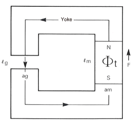
Although the current in an electric circuit rarely leaks outside the circuit, as the difference in the magnetic permeability between the conductor yoke and insulated area in a magnetic circuit is not very large, leakage of the magnetic flux also becomes large in reality. The amount of the magnetic flux leakage is expressed by the leakage factor σ, which is the ratio of the total magnetic flux Φt generated in the magnetic circuit to the effective magnetic flux Φg of the vacant space.
![]()
In addition, the loss in the magnetic flux due to the joints in the magnetic circuit must also be taken into consideration. This is represented by the reluctance factor f. Since the leakage factor σ is equivalent to the increase in the vacant space area, and the reluctance factor f refers to the correction coefficient of the vacant space length, the corrected magnetic resistance becomes as follows.
![]()
The inverse of this magnetic resistance is known as permeance (P) and generally, this permeance is used in the calculations. Substituting this in Equation (1), P then becomes as follows.
![]()
If you assume the cross-sectional area of the magnet as am, the length as ℓm, the demagnetized field in the magnet as Hd, the magnetic flux density as Bd, and the magnetic flux density in the magnet to be uniform, then F and Φt are expressed as follows.
![]()
Based on Equation (6), the permeance coefficient is determined by the following equation.
![]()
Substituting Equation (5) into this equation, the permeance coefficient becomes as follows.
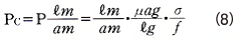
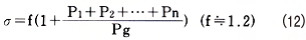
Therefore, the external permeance as seen from the magnet can also be said to be the permeance coefficient of the magnet when converted to a per unit volume figure. The above equation shall serve as the basic equation for determining the permeance. Although the reluctance factor f is approximately 1.1 – 1.3 and no big error will result if a normal value of 1.2 is assumed, the leakage factor σ has to be determined based on calculation since it will fluctuate to a certain extent. Based on Equation (3), the leakage factor σ is determined as follows.
![]()
Since Ft/Fg is equivalent to the reluctance factor here, σ then becomes
![]()
Since Pt is the sum of the vacant space permeance and the leakage permeance, it therefore becomes

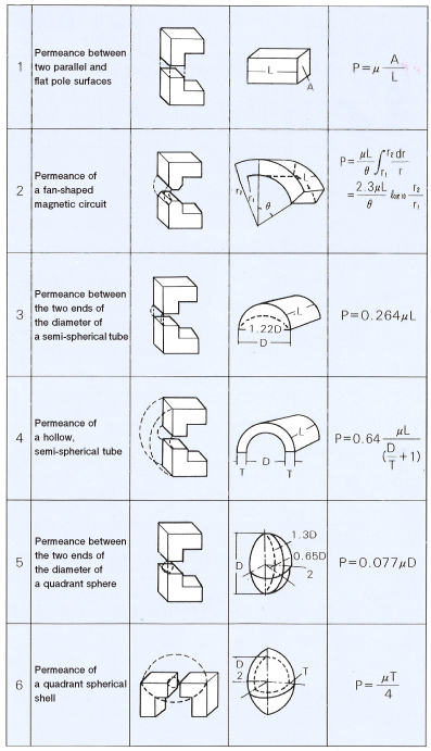
Although Pg can be computed easily as Pg=μag/ℓg, as the leakage permeance is quite complex, the respective terms are generally simplified and computed as shown in Figure 8. The respective permeance is determined in this manner to compute σ.
Permeance of Various Types of Spaces
Permeance Coefficient in a Standalone Magnet
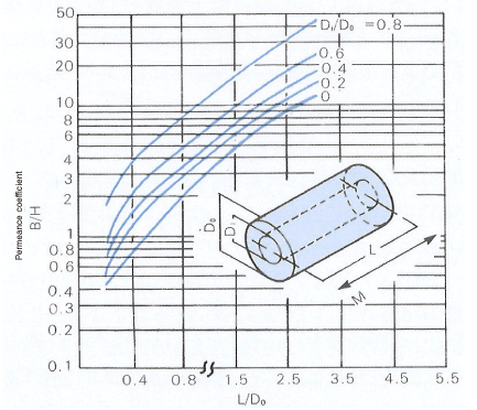
Generally, a magnet is used with an iron plate attached to the pole. It is also not rare for a magnet to be used on its own without a magnetic material attached. Refer to Figure 9 – Figure 11 when designing such a magnetic device.
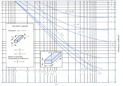
Relationship between the proportion and the permeance coefficient of a square magnet
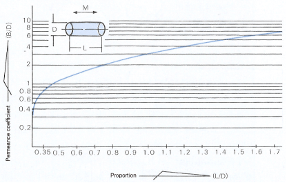
Relationship between the proportion (L/D) and the permeance coefficient of a cylindrical magnet
Permeance coefficient of a tubular magnet magnetized in the direction of the axis (B/H)